|
 |
 Автор: Williams Автор: Williams
 Дата: 15 июня 2025 Дата: 15 июня 2025
 Просмотров: 314 Просмотров: 314 |
| |
Sensors & Software EKKO_Project 2025 V6 R2.1 build 8238
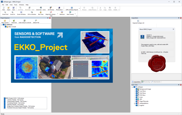
EKKO_Project is the all-inclusive software solution for managing, displaying, processing and interpreting GPR data. Once the Ground Penetrating Radar (GPR) data collection in the field is complete, the next step is to pull out the key information and images and generate a final report. The EKKO_Project software makes complex GPR analysis easy with intuitive tools to organize, edit, process and plot your GPR data. Powerful visualization, analysis and integration tools allow you to quickly and easily produce impressive reports. EKKO_Project consists of a base program with optional modules. The base package provides file organization, quick visualization of your project information in a single window and automated reporting. EKKO_Project works with project .gpz files automatically exported from current GPR systems. An embedded database structure allows all GPR data and ancillary files (GPS, topography, photos, notes, etc.) to be housed in a single .gpz file for a specific project. A project file could contain a single GPR line or several hundred lines from a complex survey. Legacy .dt1 and .hd files can also be imported. Any available project information can easily be added to the .gpz file, providing a single point for all your survey information. |
| |
 Читать статью дальше (комментариев - 1)
| |
|
 |
 Автор: Williams Автор: Williams
 Дата: 14 июня 2025 Дата: 14 июня 2025
 Просмотров: 2 845 Просмотров: 2 845 |
| |
Autodesk Autocad 2026.0.1 alternative patch
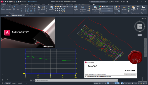
AutoCAD 2026, как и предыдущие версии, является САПР (Системой Автоматизированного Проектирования) от Autodesk, предназначенной для создания 2D и 3D чертежей, а также для работы с моделями. Ключевые нововведения в 2026 версии включают усовершенствования в работе с умными блоками и повышенную производительность.
Основные улучшения и новые возможности AutoCAD 2026.
Умные блоки:
Функция "Умные блоки: поиск и преобразование" получила значительные улучшения, позволяющие автоматически находить и преобразовывать в блоки не только геометрические объекты, но и текстовые элементы, а также существующие блоки.
Улучшенный поиск и преобразование:
В новой версии упрощен процесс поиска и преобразования объектов в блоки. Теперь это можно сделать через ленту, просматривать результаты в специальном режиме и управлять процессом через панель инструментов.
Новые переменные:
Введены новые переменные, такие как TEXTTOATTRIBUTE, для управления поиском текста и BSEARCHINCLUDEEXISTINGBLOCKS для управления включением существующих блоков в процесс преобразования.
Повышенная производительность:
Autodesk AutoCAD 2026, как и предыдущие версии, стремится к оптимизации рабочего процесса и повышению производительности за счет специализированных инструментов и функций. |
| |
 Читать статью дальше (комментариев - 17)
| |
|
 |
 Автор: Williams Автор: Williams
 Дата: 11 июня 2025 Дата: 11 июня 2025
 Просмотров: 273 Просмотров: 273 |
| |
Thunderhead Pathfinder 2024.2.1209
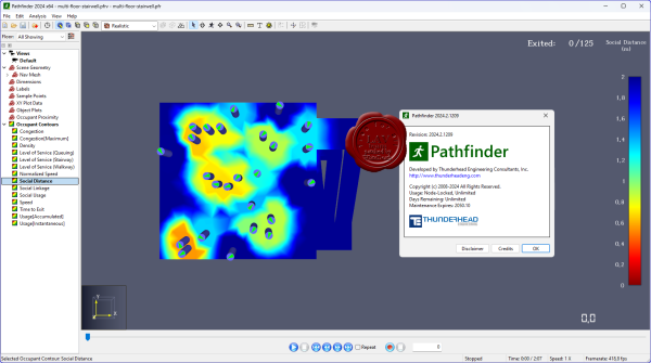
Pathfinder - симулятор эвакуации, использующий современные методы исследований в области информатики для моделирования движения людей, опираясь на технологии, применяемые в игровой и компьютерной графике. Pathfinder предоставляет инструменты, необходимые для проектирования надежных решений относительного расположения зданий и конструктивных систем противопожарной защиты. Несколько режимов моделирования и настраиваемых свойств пассажиров позволит вам с легкостью исследовать различные сценарии, позволяющие выполнить осторожные и оптимистичные оценки ожидаемого времени эвакуации. Pathfinder является агентом-симулятором, т.е. каждый житель использует набор отдельных параметров и принимает решения независимо друг от друга на протяжении всей симуляции. В дополнение к передовому симулятору движения пешеходов, Pathfinder включает в себя интегрированный пользовательский интерфейс и 3D-визуализацию результатов.
Tutorials |
| |
 Читать статью дальше (комментариев - 1)
| |
|
 |
 Автор: Williams Автор: Williams
 Дата: 10 июня 2025 Дата: 10 июня 2025
 Просмотров: 162 Просмотров: 162 |
| |
Thunderhead Ventus 2024.2.1120
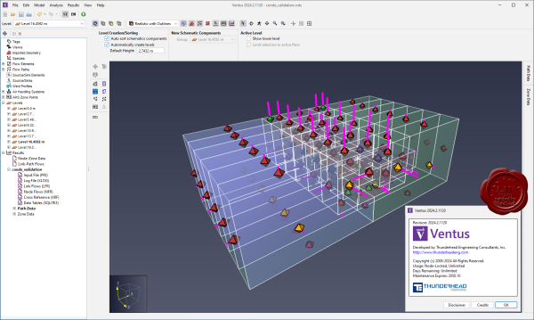
Ventus is designed to provide a pressurization simulation for smoke control analysis. The simulation is performed by CONTAM, an open-source application maintained and developed by NIST.
Like PyroSim and FDS, Ventus provides a premium user experience for industry leading simulation software. By utilizing our expertise in delivering 3D modeling applications for fire protection eningeering, Ventus will exceed the demands of CONTAM users who want to accelerate their smoke control projects.
- Ventus allows users to build 3D models of pressure zones based on actual building geometry.
- Ventus manages multi-variable scenarios for simplified batch CONTAM simulation and analysis.
- Ventus tabulates results data for multiple scenarios into digestible CSV data and 3D visuals.
Whether for stairwells, atriums, or underground buildings, proper air handling systems must be designed for pressurized smoke control in case of emergency. Ventus provides a clear and efficient path from modeling a building to understanding temperatures, pressures, and densities so that the proper solution can be reached.
Thunderhead Engineering supports you every step of the way. Whether you want in-depth training or self-taught materials, you can learn performance-based design modeling with greater efficiency and proficiency. We design our software for anyone to learn, and our customers are delighted when our support team helps them succeed. |
| |
 Читать статью дальше (комментариев - 1)
| |
|
 |
 Автор: Williams Автор: Williams
 Дата: 9 июня 2025 Дата: 9 июня 2025
 Просмотров: 216 Просмотров: 216 |
| |
Thunderhead PyroSim 2024.2.1209

PyroSim – это пользовательский интерфейс для программы Fire Dynamics Simulator (FDS). Полевая модель FDS может предсказывать распространение дыма, температуры, угарного газа и других опасных факторов во время пожара. Результаты моделирования используются для обеспечения безопасности зданий при проектировании, определения безопасности существующих зданий, реконструкции пожаров при расследованиях, и помощи в тренировках пожарных. FDS – мощный инструмент для моделирования пожара, разработанный Национальным институтом стандартов и технологий (National Institute of Standards and Technology – NIST). FDS моделирует сценарии пожара с использованием вычислительной гидродинамики (CFD), оптимизированной для низкоскоростных температурно-зависимых потоков. Такой подход оказывается очень гибким, и может быть применен к различным пожарам, начиная от горения в печах и до пожаров на нефтяных танкерах. Также с помощью FDS может быть выполнено моделирование, не включающее горение, например, работа вентиляции в зданиях. Расчетная модель FDS и программа для визуализации Smokeview тесно встроены в PyroSim.
Tutorials |
| |
 Читать статью дальше (комментариев - 0)
| |
|
 |
 Автор: Williams Автор: Williams
 Дата: 8 июня 2025 Дата: 8 июня 2025
 Просмотров: 1 165 Просмотров: 1 165 |
| |
nanoSoft nanoCAD Suite 2025 v25.0 Multilingual (except Russian)
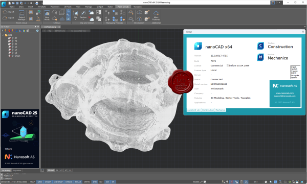
nanoCAD – российская САПР-платформа, содержащая все необходимые инструменты базового проектирования. Знакомый интерфейс, прямая поддержка формата *.dwg и расширяемость делают nanoCAD лучшей на сегодня альтернативой при выборе инженерной платформы для любой отрасли. Российская универсальная САПР-платформа, содержащая все необходимые инструменты базового проектирования, выпуска чертежей и разработки приложений с помощью открытого API. Знакомый интерфейс, непосредственная поддержка формата *.dwg и расширяемость делают ее альтернативой №1 при переходе на новые базовые решения. Платформа nanoCAD постоянно развивается и совершенствуется. При разработке восьмой версии основное внимание было уделено повышению точности математического аппарата и удобства работы с программой, развитию корпоративных функций и интеграции с BIM-системами.
Подробнее |
| |
 Читать статью дальше (комментариев - 9)
| |
|
 |
 Автор: Williams Автор: Williams
 Дата: 7 июня 2025 Дата: 7 июня 2025
 Просмотров: 382 Просмотров: 382 |
| |
Bentley Offshore 2025
SACS 25.00.00.136, MOSES 25.00.00.280, Maxsurf 25.00.00.280

Analysis and design of offshore platforms and vessels are some of the greatest technical challenges in the offshore engineering profession. To address this, Bentley proudly offers SACS, MOSES and Maxsurf – a range of software proven in offshore and marine industry-specific capabilities.
SACS Offshore Structure Advanced is offshore structural analysis software that helps you optimize design to ensure compliance, understand behavior, and accurately predict performance of all types of offshore structures.
Conduct comprehensive analyses – including full nonlinear, dynamic, and impact effects – to predict how your platform or topside structure will behave under a host of conditions. Model pile-soil interactions and apply wind, wave, seismic, ship impact, dropped object, and blast loads for a full range of likely effects.
Customizable templates within a common structural model make it easier to manage multiple analyses. Automatically pass data from one analysis step to another using industry-standard methodologies. Automated workflows simplify the management of large and complex models, which encourages your team to explore more design options.
Built-in checking provides assurance that your designs comply with offshore international codes, including API, AISC, EC, ISO, DNV, and Norsok. The software enables you to filter for critical conditions and provide compliance documentation.
MOSES is integrated offshore simulation software. This advanced hydrostatic and hydrodynamic software ensures that you can apply industry best practices to installation and design sequences, while exploring design alternatives within a unified modeling environment. Bentley MOSES integrated simulation software helps you minimize offshore project risks with optimal designs. Easily analyze floating systems across a range of operating conditions using simulation language to define environmental conditions, specify mooring configurations, and run integrated solvers in a unified environment. Use interactive graphical tools specific to offshore structures to prepare models of your vessels and floating systems. Help ensure accurate loading definition by visualizing tank and compartment models during modification. Leverage comprehensive and customizable scripting tools and pre-defined macros to explore design alternatives and manage complex installation sequences.
These modules are included in MOSES ULTIMATE:
- MOSES Solver: Allows you to consider all type of forces acting on your floating systems, including hydrostatic, hydrodynamic, inertial, and mooring forces.
- MOSES Language: Provides a unique, flexible, and powerful way of specifying system behavior and analyzing performance for different installations and operational conditions.
- Hull Modeler: Gives you an interactive way to create 3D hull shapes.
- Stability Modeler: Allows you to model compartmentation and load case management.
- Motions Modeler: Provides the tools for modeling environmental and mooring inputs.
- Hull Mesher: Enables you to graphically represent structural models.
- Basic Connectors: Offer a generalized way of modeling lifting slings, anchor lines, mooring lines, nonlinear springs, pins, fenders, and other items that connect two bodies or a body to the ground. Connectors can be tension-only or compression-only and custom connectors can be defined.
- Strip Theory: Provides a fast and proven way to predict the motions of your vessel. It is well suited for barge transports and any vessel that is slender in its L/B (length/beam) ratio.
- 3D Diffraction: Allows you to predict motions for non-ship shaped hulls and account for surge. Adaptive meshing automatically increases panel mesh density as required.
- Time Domain: Perform time-history simulations on single or multi-body systems to predict performance. The Time Domain module can perform a time history simulation on any single or multi-body system. Starting from the frequency domain results, and taking into account mooring, current, and wave forces, the Time Domain module provides fast computation of full system response. Customizable reporting and automatic generation of system response animations allow easy understanding and communication of results.
- Pipe and Rod Elements: Handle mooring line dynamics with accurate calculations or response, including accounting for large deflections. This allows modelling and analysis of anchor lines, mooring lines, TLP (tension leg platform) tendons, rigid risers, and pipelines.
- Structural Solver: Enable structural analysis, as well as spectral fatigue analysis of topside and cargo structures. It supports beam and plate elements and can import structures from SACS.
- Jacket Launch: Perform six-degree-of-freedom time domain simulations of jacket launches from a barge into water.
- Generalized Degrees of Freedom: Understand the effect of structural deformation and flexibility on buoyancy, frequency response, and loadout calculations. It can also be used to consider the hydrodynamic interaction between two vessels.
Maxsurf is naval architecture software ideal for the design of marine vessels. Maxsurf includes capabilities for hull modeling, stability, motions and resistance prediction, structural modeling, structural analysis, and export to vessel detailing. Maxsurf operates from a single parametric 3D model in order to ensure smooth communication and coordination across various involved in the project. Ensure compliance with international stability criteria and balance vessel performance requirements using integrated analysis tools. Perform a range of analyses including intact and damaged stability, resistance and motions prediction, and structural analysis. Create complex 3D hull forms for any type of vessel using wizards and interactive sketch tools. Systematically explore design alternatives by making measured changes to models with easy-to-use tools. Apply transformations to increase the productivity of the initial hull design process. Perform faster hull form variation and analysis with team-based concurrent modeling on a common 3D parametric model. Easily visualize and assess design alternatives within a consistent graphical environment with smooth data flow.
Multiframe Structural Engineering Software provides linear and non-linear analysis, static and dynamic options and buckling calculations. These analysis options are complemented by a full range of analysis-related modeling tools like master-slave, prescribed displacements, springs, thermal effects, offset members, additional masses and much more. Other modules allow you to draw section shapes and install them in the sections library and perform design checks for a range of design codes. Multiframe Automation allows you to prepare design calculations in Excel and link them directly with your Multiframe model. An ever expanding range of design add-ons also allows you to simplify steel code checking and optimization. |
| |
 Читать статью дальше (комментариев - 5)
| |
|
 |
 Автор: Williams Автор: Williams
 Дата: 6 июня 2025 Дата: 6 июня 2025
 Просмотров: 711 Просмотров: 711 |
| |
BuildSoft PowerConnect 2025 build 9168.7353
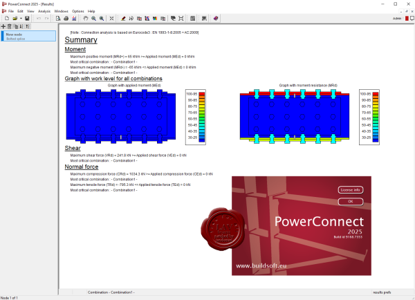
Steel connection software.
PowerConnect is the perfect software to design quick and easy different types of steel connections. Watch some videos, look at the brochures or read more about the advantages of PowerConnect.
Moment connections
- End plate, angles or welded
- Extras: haunches, stiffeners ...
- Optimal bolt positions
- M, V and N
- Rotational stiffness graph
Shear connections
- Shear end plate
- Fin or single plate
- Angles
- Optimal bolt positions
- V and N
Column bases
- I or rectangular cross-section
- Stiffeners and cramps
- Straight or bent anchors
- M, V and N
- Rotational stiffness graph
Tubular connections
- Type T, Y, DY, X, K, N, KT & DK
- Round, square, rectangle or I cross-sections
- M_i, M_o and N
Optimization of bolt positions according to EN 1993-1-8, IS 800 and AISC-LRFD.
Fast identification of undersized and oversized components through colour coding on connection geometry of each component’s level of exhaustion. |
| |
 Читать статью дальше (комментариев - 8)
| |
|
 |
 Автор: Williams Автор: Williams
 Дата: 5 июня 2025 Дата: 5 июня 2025
 Просмотров: 528 Просмотров: 528 |
| |
BuildSoft Diamonds 2025 build 9173.25028
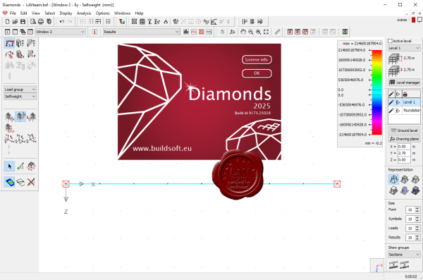
Software for structural analysis of steel, concrete and timber constructions.
Diamonds is the perfect software for analysis of steel, concrete and timber structures. Watch some videos, look at the brochure or read more about the advantages of Diamonds. Each Diamonds license can be extended with additional modules such as fire resistance, seismics, moving loads.
Steel
On executing the Eurocode and AISC steel resistance and buckling verifications, the appropriate cross-section classification is taken into account. Buckling lengths and lateral torsional buckling supports are specified in no time or automatically calculated. Based on these checks Diamonds performs a cross-section optimization. Connections can be transferred to PowerConnect.
- Eurocode 3 (UK, DE, ES, PL, ...) and AISC- LRFD
- Extendable built-in section library
- Cross section classification
- Buckling length calculation
- Lateral torsional buckling supports
- Cross-section optimization
Concrete
Diamonds calculates the optimal reinforcement solution according to Eurocode and ACI. This serves as a starting point for a practical reinforcement definition. You can then calculate cracked deflections and crack widths for bar and plate elements or verify punching for plates and footings. For beams, complete reinforcement drawings can be generated with ConCrete Plus.
- Eurocode 2 (UK, DE, ES, PL, ...) and ACI
- Optimal reinforcement quantities
- Cracked deflection with creep
- Crack widths
- Deformation in time
- Punching verification
Timber
Diamonds calculates the deflection with creep effects, based on the service class. On execution the Eurocode timber verifications, buckling lengths and lateral torsional buckling supports are taken into account. These can be user-assigned or automatically calculated. Based on these unity check verifications Diamonds calculates the most optimal cross-sections.
- Eurocode 5 (BE, NL)
- Service class and load duration class
- Buckling length calculation
- Lateral torsional buckling supports
- Creep calculation
Diamonds’ analysis engine is based on the robust and powerful PARDISO sparse solver technology. Combining high speed performance with minimal memory usage, Diamonds will solve both simple 2D and complex 3D structural analysis models in no time. |
| |
 Читать статью дальше (комментариев - 5)
| |
|
 |
| ПОИСК ПО САЙТУ |
 |
|
 |
| КАЛЕНДАРЬ | | |
 |
| « Октябрь 2025 » |
|---|
| Пн | Вт | Ср | Чт | Пт | Сб | Вс |
|---|
| | 1 | 2 | 3 | 4 | 5 | | 6 | 7 | 8 | 9 | 10 | 11 | 12 | | 13 | 14 | 15 | 16 | 17 | 18 | 19 | | 20 | 21 | 22 | 23 | 24 | 25 | 26 | | 27 | 28 | 29 | 30 | 31 | |
|
 | |
| |
|