|
 |
 Автор: Williams Автор: Williams
 Дата: 22 ноября 2020 Дата: 22 ноября 2020
 Просмотров: 1 539 Просмотров: 1 539 |
| |
CADprofi 2021.01 build 201109
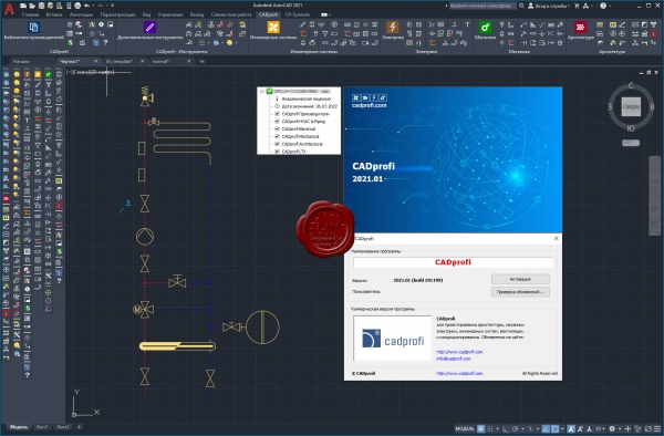
CADprofi HVAC & Piping - параметрическое CAD-приложение для проектирования технического оборудования зданий. Поддерживаются все виды технических установок: отопление, вентиляция, кондиционирование воздуха, трубопроводы и воздуховоды.
CADprofi Mechanical содержит широкий набор унифицированных деталей, стальной арматуры, стальных профилей и других компонентов, соответствующих стандартам DIN, EN, ISO и национальным нормам. Библиотека включает в себя болты, винты, шайбы, гайки, соединения, заклепки, шпильки, уголки, и детали, используемые в конструкции теплообменников и других устройств. Отличный редактор схем и проектов значительно облегчает создание чертежей гидравлических и пневматических систем.
CADprofi Architectural может быть использовано чтобы создать строительные планы, поперечные сечения и вид с фасада. Удобные функции приложения облегчают проектирование многослойных стен, архитектурное определение размеров, и быстрое создание описания конструкций. Модуль включает в себя полную библиотеку окон, дверей, мебели, и других объектов обстановки. Как дополнительная особенность, приложение может использоваться, чтобы проектировать планы эвакуации и пожаротушения.
CADprofi Electrical может быть использовано для проектирования сложных объектов, таких как электроснабжения, освещения, низковольтных систем, телекоммуникации, систем безопасности и антенных установок. Приложение содержит несколько тысяч электрических элементов и символов (светильники, распределительные устройства и многое другое) Приложение предоставляет легкий способ проектировать проводку и кабельные каналы. Среди наиболее полезных функций автоматическая нумерация (адресация) электрических цепей, и удобное проектирование и редактирование схемы подключения проводов.
|
| |
 Читать статью дальше (комментариев - 10)
| |
|
 |
 Автор: Williams Автор: Williams
 Дата: 18 ноября 2020 Дата: 18 ноября 2020
 Просмотров: 4 493 Просмотров: 4 493 |
| |
fine FIN EC Suite 2020
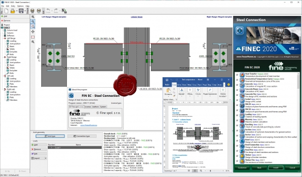
FIN EC - structural design software - contains programs for analysis of frame structures using the finite element method (FEM) and complete structural design of individual elements or details.
FIN EC Solutions:
- Structural Analysis - Structural analysis of frames and trusses using finite element method.
- Designing programs - Easy to use programs for design of structural elements.
- Structural details - Programs for design of details in steel and concrete structures.
- Fire Resistance - Easy verification of fire resistance for steel, concrete and timber structures.
- Loading - Compiling reports of structural self weight, variable, snow and wind loads.
- Cross-sections - Determination of cross-sectional characteristics.
|
| |
 Читать статью дальше (комментариев - 34)
| |
|
 |
 Автор: Williams Автор: Williams
 Дата: 16 ноября 2020 Дата: 16 ноября 2020
 Просмотров: 1 145 Просмотров: 1 145 |
| |
Geberit ProPlanner 2020 R2
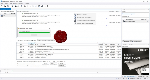
Competitive and reliable quotations are an important requirement for good planning. With its planning software ProPlanner, Geberit is providing sanitary entrepreneurs with a sophisticated tool in this regard.
The creation of cost estimates, specifications of service and quotations is a time and cost factor which cannot be underestimated. Geberit ProPlanner is customised to meet the needs of plumbers, sanitary engineers and the technical advisors at Geberit who concern themselves with the planning and calculation of medium-scale and major projects. The full range of sanitary technology – from drinking water, waste water and installation systems right through to syphonic roof drainage systems – is covered in this software package.
With a few clicks of the mouse, a fully dimensioned and calculated plan or the specification of service is created in the desired format. Schematic views, plan views, front views, 3D views of installation systems (including installation plans), as well as hydraulic, material, quotation and calculation lists are immediately available as output results. Various interfaces to other calculation programs are available for further processing of the planning results. Geberit ProPlanner automatically provides every detail in optimum, clear visualisation. Regular updates ensure that the software always operates with the latest standards and regulations. |
| |
 Читать статью дальше (комментариев - 8)
| |
|
 |
 Автор: Williams Автор: Williams
 Дата: 12 ноября 2020 Дата: 12 ноября 2020
 Просмотров: 3 782 Просмотров: 3 782 |
| |
Agisoft Metashape Pro v1.7.0 build 11340 x64
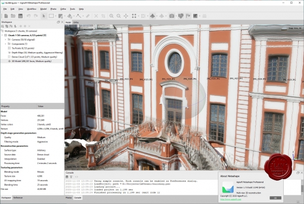
Agisoft Metashape Professional - это передовое программное обеспечение, максимально раскрывающее возможности фотограмметрии, а также включающее в себя технологии машинного обучения для анализа и пост-обработки, что позволяет получать максимально точные результаты.
Metashape позволяет обрабатывать изображения, получаемые с помощью RGB- или мультиспектральных камер, включая мультикамерные системы, преобразовывать снимки в плотные облака точек, текстурированные полигональные модели, геопривязанные ортофотопланы и цифровые модели рельефа/местности (ЦМР/ЦММ).
Дальнейшая постобработка позволяет удалять тени и искажения текстур с поверхности моделей, рассчитывать вегетационные индексы и составлять файлы предписаний для агротехнических мероприятий, автоматически классифицировать плотные облака точек и т.д.
Возможность экспорта во все внешние пакеты для постобработки делает Agisoft Metashape Professional универсальным фотограмметрическим инструментом.
|
| |
 Читать статью дальше (комментариев - 23)
| |
|
 |
 Автор: Williams Автор: Williams
 Дата: 8 ноября 2020 Дата: 8 ноября 2020
 Просмотров: 9 480 Просмотров: 9 480 |
| |
CSI ETABS v19.0.0 build 2277 x64
The innovative and revolutionary new ETABS is the ultimate integrated software package for the structural analysis and design of buildings. Incorporating 40 years of continuous research and development, this latest ETABS offers unmatched 3D object based modeling and visualization tools, blazingly fast linear and nonlinear analytical power, sophisticated and comprehensive design capabilities for a wide-range of materials, and insightful graphic displays, reports, and schematic drawings that allow users to quickly and easily decipher and understand analysis and design results.
From the start of design conception through the production of schematic drawings, ETABS integrates every aspect of the engineering design process. Creation of models has never been easier - intuitive drawing commands allow for the rapid generation of floor and elevation framing. CAD drawings can be converted directly into ETABS models or used as templates onto which ETABS objects may be overlaid. The state-of-the-art SAPFire 64-bit solver allows extremely large and complex models to be rapidly analyzed, and supports nonlinear modeling techniques such as construction sequencing and time effects (e.g., creep and shrinkage). Design of steel and concrete frames (with automated optimization), composite beams, composite columns, steel joists, and concrete and masonry shear walls is included, as is the capacity check for steel connections and base plates. Models may be realistically rendered, and all results can be shown directly on the structure. Comprehensive and customizable reports are available for all analysis and design output, and schematic construction drawings of framing plans, schedules, details, and cross-sections may be generated for concrete and steel structures.
ETABS provides an unequaled suite of tools for structural engineers designing buildings, whether they are working on one-story industrial structures or the tallest commercial high-rises. Immensely capable, yet easy-to-use, has been the hallmark of ETABS since its introduction decades ago, and this latest release continues that tradition by providing engineers with the technologically-advanced, yet intuitive, software they require to be their most productive.
|
| |
 Читать статью дальше (комментариев - 69)
| |
|
 |
 Автор: Williams Автор: Williams
 Дата: 4 ноября 2020 Дата: 4 ноября 2020
 Просмотров: 460 Просмотров: 460 |
| |
ADINA v9.6.3 x64
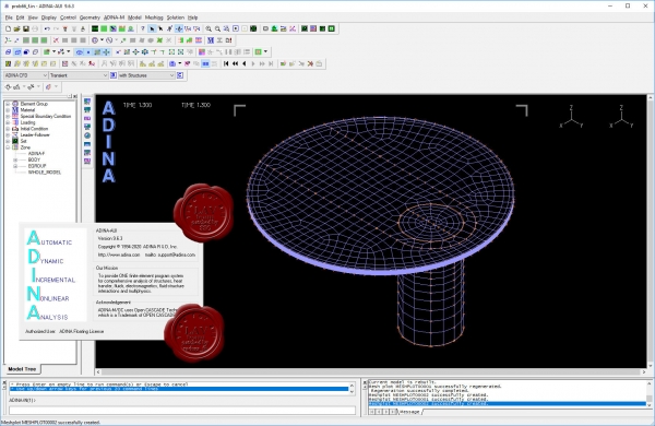
ADINA (Automatic Dynamic Incremental Nonlinear Analysis) - универсальная программа, работающая на основе метода конечных элементов, используемой для инженерных линейных и нелинейных расчётов. ADINA позволяет решать структурные и температурные задачи, рассчитывать течение, проводить мультифизические и электростатические симуляции. Внедрение программы при разработке или производстве продукта является лучшим решением для снижения затрат на производство прототипов и сокращения времени их тестирования. Современные расчётные методы, лежащие в основе программы ADINA , выгодно отличают её от остальных программ благодаря точным и надёжным результатам решения нелинейных задач.
Основные функциональные возможности пакета:
- Линейный анализ конструкций.
- Высоконелинейный анализ конструкций.
- Тепловой анализ.
- Гидродинамика.
- Взаимодействие потоков с конструкциями.
NX Nastran использует ADINA как модуль нелинейных расчетов.
Пакет ADINA состоит из следующих модулей:
- ADINA Structures - модуль расчёта статической и динамической прочности твёрдых тел и конструкций. Расчёт может быть проведён как в линейной, так и в высоконелинейной постановке с учётом нелинейности материала, больших деформаций и контакта.
- ADINA CFD – программный комплекс для моделирования течений сжимаемой и несжимаемой жидкости, использующий конечно-объемную и конечно-элементную дискретизацию.
- ADINA Thermal - программный модуль для решения задач теплопереноса в твёрдых телах и конструкциях.
- ADINA-FSI - модуль, предназначенный для анализа взаимодействия потока и конструкции, причём возможно рассмотрение высоконелинейного поведения материала вследствие больших перемещений, неупругости, контакта и температурной зависимости.
- ADINA-TMC - программный модуль, предназначенный для решения связанных термопрочностных задач, когда термические явления влияют на прочностные, и наоборот.
- ADINA User Interface (AUI) - пре- и постпроцессорный модуль, дающий возможность создавать и редактировать геометрические и конечно-элементные модели и осуществлять визуализацию результатов расчёта. Совместим со всеми модулями комплекса.
Дополнительные модули:
- ADINA Modeler (ADINA M) - встраиваемый в AUI модуль, использующий графическое ядро Parasolid и обеспечивающий твёрдотельное моделирование и прямое взаимодействие с другими CAD-системами, использующими Parasolid (Unigraphics, SolidWorks, Solid Edge).
- TRANSOR for I-DEAS, Patran - отдельный модуль, дающий возможность импортировать в ADINA и экспортировать из ADINA файлы данных в форматах I-DEAS и MSC.Patran
|
| |
 Читать статью дальше (комментариев - 1)
| |
|
 |
 Автор: Williams Автор: Williams
 Дата: 2 ноября 2020 Дата: 2 ноября 2020
 Просмотров: 2 535 Просмотров: 2 535 |
| |
modri planet d.o.o. 3Dsurvey v2.12.1 x64
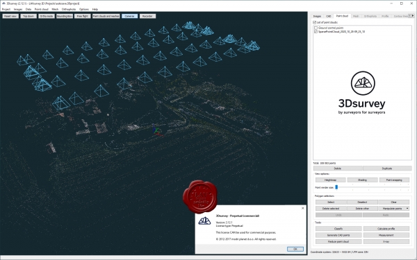
3Dsurvey is a software solution for land surveying data processing. Take a photo with any standard digital camera, import images into 3Dsurvey and produce your own orthophoto maps, digital surface models and calculate volumes faster and more easily. Data is processed automatically based on matching algorithms. Use our smart tools to be even more efficient.
|
| |
 Читать статью дальше (комментариев - 19)
| |
|
 |
 Автор: Williams Автор: Williams
 Дата: 27 октября 2020 Дата: 27 октября 2020
 Просмотров: 6 185 Просмотров: 6 185 |
| |
CSI SAP2000 v22.2.0 build 1663 x64
CSI SAP2000 - cистема трехмерного статического и динамического анализа методом конечных элементов и проектирования сооружений.
SAP2000 следует принципам, основными чертами которых являются современный, интуитивно понятный и универсальный пользовательский интерфейс, основанный на уникальном расчетном ядре и инструментах проектирования конструкций для инженеров, разрабатывающих объекты транспортной инфраструктуры, промышленные и гражданские здания, спортивные сооружения и другие объекты.
Начиная с трехмерной объектно-ориентированной рабочей среды моделирования и до широчайшего спектра опций расчета и проектирования конструкций, комплексно интегрированных в один мощный пользовательский интерфейс, SAP2000 – это наиболее интегрированный, производительный и практичный расчетный комплекс общего назначения, существующий на сегодняшнем рынке. Интуитивно понятный интерфейс позволяет Вам создавать модели конструкций в кратчайшие сроки без долгого процесса обучения. Сегодня Вы можете использовать SAP2000 для всех Ваших задач по расчету и проектированию, в том числе и для небольших повседневных задач.
Комплексные модели могут быть созданы и разбиты на конечные элементы с использованием встроенных шаблонов. Интегрированные инструменты проектирования конструкций способны автоматически сгенерировать ветровые, волновые, нагрузки от транспорта и сейсмические нагрузки на модель, а также выполнить полную автоматическую проверку стальных и железобетонных элементов согласно нормам проектирования различных стран.
|
| |
 Читать статью дальше (комментариев - 33)
| |
|
 |
 Автор: Williams Автор: Williams
 Дата: 19 октября 2020 Дата: 19 октября 2020
 Просмотров: 4 090 Просмотров: 4 090 |
| |
ArqCOM CivilCAD Suite build October, 2020
for any version of AutoCAD, ZWCAD, BricsCAD
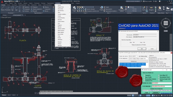
CivilCAD, creado por ARQCOM, es el software diseñado para crear funciones adicionales que automatizan y simplifican las tareas dentro de AutoCAD Full, Bricscad PRO y ZWCAD+ Professional, cubriendo diversas necesidades del profesional de la Ingeniería Civil y Topografía de habla hispana; utilizado por dependencias de gobierno, constructoras y universidades.
Con CivilCAD, puede obtener rápidamente perfiles, secciones, curvas de nivel, cálculo de volúmenes en plataformas y vialidades, cuadros de construcción, subdivisión de polígonos, entre otras más de 100 rutinas.
La licencia base de CivilCAD sólo incluye rutinas de topografía básica (ver rutinas). Existen 6 módulos adicionales que agregan rutinas especializadas a su licencia base de CivilCAD y son:
- Cálculo de Redes de Agua Potable
- Cálculo de Redes de Alcantarillado
- Diseño de Carreteras SCT
- Exportación de Datos al Programa Curva Masa SCT
- Cálculo de Redes de Alcantarillado Pluvial ADS
- Interfase con Google Earth
|
| |
 Читать статью дальше (комментариев - 22)
| |
|
 |
 Автор: Williams Автор: Williams
 Дата: 16 октября 2020 Дата: 16 октября 2020
 Просмотров: 3 592 Просмотров: 3 592 |
| |
САПРОТОН NormCAD v11.6 x32+x64
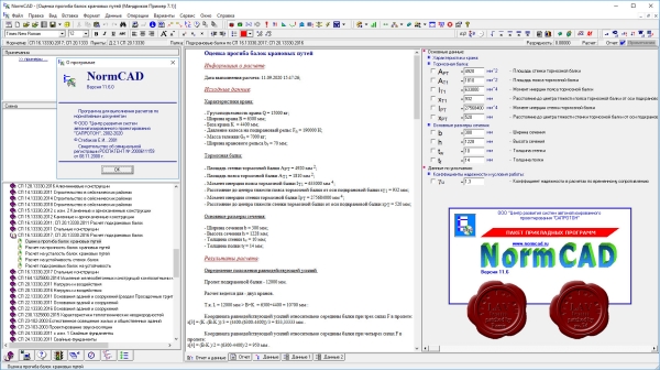
NormCAD выполняет расчеты строительных конструкций по СНиП и готовит проектную документацию для представления заказчику и в органы экспертизы:
- расчет стальных конструкций (расчет балок, колонн сплошного и составного сечения, профнастила и узлов ферм из гнутых профилей);
- расчет железобетонных конструкций (расчет балок, колонн, стен и плит: подбор арматуры, проверка сечений - в т.ч. тавровых и двутавровых, косое внецентренное сжатие, расчет круглых колонн и колонн с распределенной арматурой, трещиностойкость, проверка прогиба, расчет на смятие и продавливание);
- расчет каменных и армокаменных конструкций (проверка сечений - прямоугольных и тавровых на центральное и внецентренное сжатие, растяжение, срез, трещиностойкость и смятие);
- расчет фундаментов;
- теплотехнический расчет (сопротивление теплопередаче и паропроницанию стен, покрытий, перекрытий и светопрозрачных конструкций).
- другие строительные и машиностроительные расчеты.
Главное преимущество - на сегодня это единственная программа, в которой расчет оформляется в виде текстового документа (в формате Word), подобному созданному опытным конструктором вручную, что позволяет легко проконтролировать любую часть расчета.
О новом в версии 11.6 тут |
| |
 Читать статью дальше (комментариев - 17)
| |
|
 |
| ПОИСК ПО САЙТУ |
 |
|
 |
| КАЛЕНДАРЬ | | |
 |
| « Октябрь 2025 » |
|---|
| Пн | Вт | Ср | Чт | Пт | Сб | Вс |
|---|
| | 1 | 2 | 3 | 4 | 5 | | 6 | 7 | 8 | 9 | 10 | 11 | 12 | | 13 | 14 | 15 | 16 | 17 | 18 | 19 | | 20 | 21 | 22 | 23 | 24 | 25 | 26 | | 27 | 28 | 29 | 30 | 31 | |
|
 | |
| |
|