Автор: Williams Дата: 28 февраля 2025
Просмотров: 361
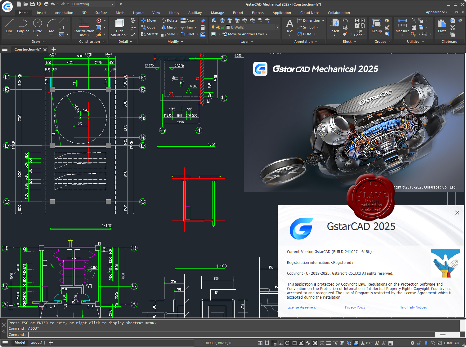
Gstarsoft GstarCAD Mechanical 2025 build 241027
Covering all fields of mechanical design, GstarCAD Mechanical is professional designing and drawing software specially built for manufacturing. No matter what kind of design task you are facing, GstarCAD Mechanical helps to complete your ideas perfectly.